|
| Warning-Caution-Warning |
|
|
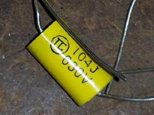
| Do not use these Caps-Read below |
Ken, W0HRO picked up some replacement caps at the Orlando Hamfest last winter. After bringing them home and checking
them, he discovered that they were inferior. He says that a high percentage of these capacitors will not perform to their
voltage rating. Ken says that he always had good luck with Bob's Caps* and will continue to order from Bob.
*
Bob Piekarz, of LaGrange Park Illinois sells a large line of most needed replacement caps and you can click a link to Bob
below.He has reasonable prices and ships fast.
Click here for Bob's Capacitors and other radio items
************************************************************************ AFTER NET TECH SESSION
OF 26 JAN 13 CONDUCTED BY JOHN, K9KEU:
After net Session Balanced line and Antenna tuners:
WB9IMR: How does an auto tuner's power rating relate
to an AM signal
with carrier.
N9WQ , K9OA, W8TOW participated in the discussion but no real
consensus.
Suggestion to call the manufacturer before purchase.
KB9ENH suggested a Millen Autotuner, N9WQ SUGGESTED A COLLINS
180L or a
Harris. These are all Military units.
K9KEU asked : Has any one experience using 2 pieces of coax
as a
balanced feed line or experience using a balun outside the house and
coax to the radio?
K9QPM Used
an external balun and 450 ohm line to feed an rhombic ant.
He uses a big Tentec tune and can run full output from
a Johnson
thunderbolt.
W8TOW is using twin coax and link coupled tuners to feed dipoles with
good results
W8NWF
has used a link coupled tuner to feed twisted pair feedline and a
dipole with good results.
WJ9Y has used a link
coupled tuner using a series capacitor rather than
a mechanically coupled coil to tune the link with good results.
***************************************************************
Anote received from Pierre, K9EYE:
Many of you know that there are many problems with interference from line noise to bad insulators
, to interference on power poles and light poles alike.
All this interference is a violation to fcc.
one of my friends wa9ujr, got tired of getting the run around by calling the 800 number. so he
sent a registered letter to the CEO of commonWealth Edison it was within a week he got action and the problems in his area
resolved.
So I want to share the address and the ceo of CommonWealth Edison with you all so you can write
a registered letter to her to get our complaints taken care of.
In my area it was noise from power light poles and they were taken care of.so here is the info.
Common wealth Edison, Executive offices
Ann Pramaggiore
440 South LaSalle 33rd floor
Chicago, IL 60605
Phone : 312-394-3934
Another problem is the high efficient furnaces k9dci, can support me on this he was a major factor on
helping me with the manufacture, Armstrong, so much they could not resolve the interference , that they gave me my money back,
and the installer installed a York furnace at no charge, that does not put out interference.
You see our fcc license has quite a bit of clout when it comes to the fcc rules and interference, we
be sure that we do not cause any, and others should not cause to us.
I hope you all do not mind me sharing this info, like anything else, we need to be heard.
So if you have Electrical interference please you must send a registered letter to the CEO of CommonWealth
Edison and you will get action.
Well you can eliminate the furnace noise too, I purchased a new furnace made by Armstrong, the
line noise that came on was awful . I told them that they were in violation of fcc part 15, they did not laugh at me, they
bought back my furnace and gave me 300.00 extra to replace, York furnace was the one I replaced it with that and no line noise.
Just remember that we have the fcc and the arrl behind us, and u.s.a. made products must conform.
Notice that little sticker that says fcc inspected wellif is on there and you have noise someone
falsified the inspection.
Remember you have rights just like me..
accessibility is a right not a privilege.
Pierre Berube. K9EYE
and Leader Dog Smokey
****************************************************************************************
*****************************************************************************
AFTER NET TECH SESSION OF 29 DECEMBER 2012
Q. HOW DO YOU CLEAN GRIME AND TOBACCO TAR
FROM VINTAGE CHASSIS AND PANELS?
WA9YEQ- STARTING FLUID WORKS WELL BUT DUE TO IT'S HIGH FLAMMABILITY GREAT CARE MUST
BE USED.
K9QPM- BLUE CORAL DELICATE GRIME REMOVER.
W0HRO-
KRUD KUTTER LOWE'S BUT BE CAREFUL OF LETTERING
. TEST ON SURFACE BEFORE USING.
AB9MQ-MACHINE OIL OR 10W-40 ON A RAG WORKED INTO THE GRIME OR DEOXIT WORKS WELL.
K9EYE-AVON
SKIN SO SOFT WORKS WELL AND MAKES YOUR RIG SMELL GOOD.
W9RMB-SOAP AND WATER THEN USE COMPRESSED AIR TO DRY.
WA9YBW-WB4HFN.COM
WEBSITE A GOOD RESOURCE. HE STEAM CLEANS HIS BOAT ANCHORS.
W8NWF-SOAP AND WATER THE BEST.
Q. IS THERE AN
EASIER WAY TO TROUBLE SHOOT AVC PROBLEMS THAN JUST START CHANGING COMPONENTS?
W0HRO-START BY CHANGING ALL THE BYPASS
CAPS MICA MOLD PAPER CAPS ESPECIALLY POOR
GENERAL CONSENSUS JUST START CHANGING COMPONENTS FOR A GREAT JOB CHANGE ALL
AVC BYPASS CAPS AND CHECK RESISTORS.
*************************************************************************************
AFTER NET-TECH SESSION
DANGERS IN THE SHACK
DECEMBER 8, 2012
Harry, N9CQX:
Started the session by mentioning PCBs and PCB*
is an abbreviation of Poly-chlorin-nated bi-phenyls. It was introduced in the 1920's by Monsanto Chemical Company. (used until
1970's) as an insulating fluid in ballasts, hydralic brake fluid, xformers & caps, because it had a high electrical resistance,
an excellent chemical stability and was practically non-flamable.
Mfg own trade names for pcbs (and what to watch
out for): GE-Pyranol; Cornell Dubilier-Dykanol; Sprague-Clorinol and Jard-Clorphen.
Ken, W0HRO:
Mentioned the danger of lead solder-wash hands
with use
When disconnecting coax-power-don't trust power
strips, esp when using vintage equipment that still has two prong plugs.
Looking for suggestions as to what solvents to
use when cleaning up PCB spills.
Blue Nitro gloves
Pete, W9RMB:
PCBs may be in Heath or MFJ “Cantennas”
MFJ sells non-PCB xformer oil-part # MFJ-21
Barrilium** was used in some Heath Kit heat sinks.
John, K9KEU,
PCBs most dangerous if burning
Harry, N9CQX:
PCBs are reportedly odorless
After PCB usage was stopped in the 1970's cap
manufacturers started labeling “no PCBs”
Recommends using an isolation transformer on
work bench
Pierre, K9EYE:
Cautions about exposed wires and spilling hot
drinks
He uses a dry dummy load.
John, K9QET:
Had a test kit that could test for PCBs
He uses five, 70 watt bulbs for a dummy load.
Wondered if anyone knew of asbestos usage in
rigs; he heard that the Thunderbold has some in it.
He cautioned about working with high voltage-using
the age old recommendations such as one hand (right hand) when testing HV.
Steve, W8TOW:
His MFJ with non-PCB oil-100 watts -OK but 300
Watts won't perform as well as the old Heath Kit; it wont handle continous duty, heats up and SWR rises.
Cautions about working with Bakelite***: wear
mask and use extra ventilation if drilling it.
*from Wikipedia:
PCB= polychlorinated biphenyl .
PCBs were widely used as dielectric and coolant fluids, for example in transformers, capacitors, and electric motors. Due to PCBs' environmental toxicity and classification as a persistent organic pollutant, PCB production was banned by the United States Congress in 1979 and by the Stockholm Convention on Persistent Organic Pollutants in 2001.[1] According to the U.S. Environmental Protection Agency (EPA), PCBs have been shown to cause cancer in animals, and there is also evidence that they can cause cancer in humans.[3] A number of peer-reviewed health studies have also shown a causal link between exposure to PCBs and non-Hodgkin Lymphoma, a frequently fatal form of cancer
** Beryllium is the chemical element with the symbol Be and atomic number 4. Approximately 35 micrograms of beryllium is found in the human body, but this amount is not considered harmful.[78] Beryllium is chemically similar to magnesium and therefore can displace it from enzymes, which causes them to malfunction.[78] Chronic berylliosis is a pulmonary and systemic granulomatous disease caused by inhalation of dust or fumes contaminated with beryllium; either large amounts over a short
time or small amounts over a long time can lead to this ailment. Symptoms of the disease can take up to 5 years to develop;
about a third of patients with it die and the survivors are left disabled.[78] The International Agency for Research on Cancer (IARC) lists beryllium and beryllium compounds as Category 1 carcinogens.[79]
Acute beryllium disease in the form of chemical pneumonitis was first reported in Europe in 1933 and in the United States in 1943. A survey found that about 5% of workers
in plants manufacturing fluorescent lamps in 1949 in the United States had beryllium-related lung diseases.[80] Chronic berylliosis resembles sarcoidosis in many respects, and the differential diagnosis is often difficult. It killed some early workers in nuclear weapons design, such as Herbert L. Anderson.[81]
Early researchers tasted beryllium
and its various compounds for sweetness in order to verify its presence. Modern diagnostic equipment no longer necessitates
this highly risky procedure and no attempt should be made to ingest this highly toxic substance.[3] Beryllium and its compounds should be handled with great care and special precautions must be taken when carrying
out any activity which could result in the release of beryllium dust (lung cancer is a possible result of prolonged exposure to beryllium laden dust). Although the use of beryllium compounds
in fluorescent lighting tubes was discontinued in 1949, potential for exposure to beryllium exists in the nuclear and aerospace
industries and in the refining of beryllium metal and melting of beryllium-containing alloys, the manufacturing of electronic
devices, and the handling of other beryllium-containing material.
** Bakelite, used in many products including
Radio panels and cabinets; from Wikipedia:
Bakelite (pron.: /ˈbeɪkəlaɪt/ BAY-kə-lyt), or polyoxybenzylmethylenglycolanhydride, is an early plastic. It is a thermosetting phenol formaldehyde resin, formed from an elimination reaction of phenol with formaldehyde. It was developed by Belgian-born chemist Leo Baekeland in New York in 1907.
Since Bakelite is a manufactured, synthetic plastic containing incredible
amounts of formaldehyde, asbestos and other extremely toxic polymers, those who produced these desirable products, put themselves
at risk. At the time, safety and health precautions were not mandatory. These hardworking men and women exposed themselves
to the toxins, through exposure.
.
***********************************************************************
17 November 2012 After
Net Tech Session
Subjects: Lightning
& Grounding
Rodger, WQ9E
Says all grounds to
be interconnected
Tom, W9QI
Says because lightning
likes to travel in a straight line, a friend suggested all cables to have a couple loops before passing through to shack.
He talked about a spark plug lightening arrestor. Talked about lightening tthrowing a surge into power line; he has a commercial
lightening arrestor built into his breaker panel.
Marlin, WJ9Y
Has a quick release
“pin” system for his antenna. He does a disconnect when he leaves the shack; Reports having arcing on his disconnected
feedline one time.
Bryan, WB9MCW
Recommends “Polyphaser”
-google the PDF that offered on the wed; also “Harger” of Lake Villa-check out their website for professional
grounding set-up. Bryan also agrees with having a common ground for the entire system. He also agrees with looping the cables.
See W8JI website, says a very excellent resource. Best bet is to disconnect.
Harry, N9CQX
Mentioned that lightening
can travel up as well as down, someone caught it on video recently; His method for installing ground rods, so as not to peen
the ends out of shape by pounding them in: he puts a hole in a long 2x4, about 2 feet from one end. Put vice grips on a ground
rod that is pushed into the ground. Set the 2x4 (hole) over the rod and vice grips and use the 2x4 as a lever with the fulcrum
being a ridge or something on the edge of the house. Push down on the 2x4 in stages as the vice grips are re-set.
Dave, N9WQ
Mentioned electron
flow used ignition coil example of switching polarity; He uses a fence post driver tool to set the ground rods. Call digger
hotline before driving ground rods. (Harry drove a ground rod thru a water main one time!)
Howard, WA9YBW
Mentioned past QST
Polyphaser article about grounding your station.
Bill, W9WR
Related an experience
with an individual using a hammer drill to set a ground rod.
John, K9KEU
He has a box of T-R
relays that disconnects his antenna system; says it's important to ground the antennas, not to leave them ungrounded; he has
had a couple of hits. He ties all grounds together and has the loops in his system. Mentioned using water hose to set ground
rods. Mentioned a friend who has the Polyphaser found his system acting up and realized it had dealt with a hit.
Walt, WA9LT
Mentioned that he had
some lightening hits and said there isnt much you can do againt a 'direct' hit.
*******************************************************************
I received this letter from Pete, W9RMB regarding his noise problem and what a friend did to solve his problem. It reminded
me of the MFJ Noise canceller that was mentioned by Masa, AB9MQ, during the Nov. 3rd tech session.
Harry,
These "Tech sessions" are just great and so helpfull for guys like me with old radios and not
too many people with the knowledge to service them in our "Throw away Society".
Thanks for all of your efforts!
On the line noise issue, I contacted Com Ed today and was refered to a Supervisor since the noise
is now continuous and even is heard between stations on the "Standard Broadcast Band" including being detecatable on the weaker
AM Stations. I couldn't even check in to the DX-60 Net Sunday.
He said it was probably a transformer or a cracked insulator......He said that he is "on the case"
…....I must say he was very helpful and reassuring.
I have a ham friend named Ron Gerut, K9KLT and he lives near a hospital with powerlines all over
the place and has exerienced these types of (noise) issues. Ron is a PHD and quite brilliant
and came up with a solution that puts the noise in 180 reverse phase to eliminate the line noise he had to live with.
His creation is found if you just google K9KLT. It's right there. The power line noise eliminator.…...helpful
info. for those in need.
In any event, Thanks again, for what you do fo the AM community!
Pete, W9RMB
From the K9KLT site:
By sampling noise from an antenna run broadside to a power line, and then sampling noise from the 110 VAC shack powerline--
it is possible to null out severe QRN on 40 meters by judiciously mixing these noise signals. A differential RF coupling coil
was used to create the out-of-phase signals. The entire circuit of the QRM KILLER is PASSIVE. That means perfect signal linearity
from very weak to very strong QRN.
#########################################
Technical Session following MCRN of 10 November 2012
Tom, W9QI
raised the question as to why there are different IF frequencies.
Charles, WA9YEQ
expressed interest in the same question.
Ken, W0HRO
Says the lower the IF frequency-the better the selectivity and the higher the IF gives better
image rejection. He says 455 Khz is a good comprimise. Dual conversion radios allows for first IF being low like maybe 50
Khz and then 2000KHz for the second.
Harry, N9CQX
The early radio manufacturers started using various IF freqs of their own choosing.
Rodger, WQ9E
Mentioned a few radio brands vs. various Ifs. He then offered some alignment suggestions: make
sure all the dials are properly indexed before starting an alignment. Make sure the vari-cap rotor is centered inside the
stator. Give em a good cleaning first and make sure they are set up properly. He further mentioned the advantage of using
an external receiver for tracking the HFO to keep tracking on the wrong side. If the alignment adjustments are really out
then he starts by setting the trimmer cap at ½ capacity and then adjusts the osc. He uses a noise source for RF and Mixer
stage alignment.
Ken W0HRO
Talked about the problem of setting a low end the high end back and forth but running out of
adjustment without getting a good alignment. He says that he has found that sometimes that a fixed padder or aging coils effect
the alignment range. He uses a loop of wire on the local osc tube from a freq counter. He reminds us to make sure we read
the alignment instructions for the receiver.
Clark K9OA
Talked about sweep alignment. He recently got a sweep generator.
Tom, W9QI
Bought a Rigol Function Sweep Generator and it has scope output. If Sweep Gen doesnt have that
output then set the scope to trigger with “line” to put them into sync.
Rodger, WQ9E
If you dont have a sweep gen then you can inject a signal at various frequencies and plot a
graph. Use double balanced mixer module to mix the sig gen freq with the swept output of sweep gen to create a 10.7MHz.
John, K9QET
Looking for ways to increase receiver bandwidth.
Rodger, WQ9E
You can stagger tune the IF, will sacrifice the gain. Use a small coupling cap between the primary
and secondary of the IF. You can cange the Q by using some resistive loading.
Gill, KF9KU
Has a NC109 and has problems with dial string slipping. He said that sensitivity dropped off
at low end of BC band and he put a 22 pf cap in parallel with the trimmer cap.
Rodger, WQ9E
Talked about rosin dressing and multi loop problems on dial shafts. He also mentioned backlash
on gear trains. He mentioned that a way to check proper tracking of RF and Mixer stages was to push against the cap plate
slightly and if the sensitivity doesnt drop off then its not tracking properly.
Tom, W9QI provided these links to YOUTUBE regarding alignment info:
click here for alignment info #1
click here for alignment info #2
Click here for alignment info #3
############################################################
MCRN TECH SESSION of 3 NOVEMBER 2012
Follow-up regarding the painting
discussion on Oct 20th:
John, K9KEU states that his 2 cabinets will be
stripped-powder coated for about $60
at the Ultra Coat place in Elkhorn.
A short discussion of diodes
was followed by the subject of noise incurred by hams.
Gill, K9KFU wanted to know about diodes, mounting
in series, and bleeder resistors.
Rodger, WQ9E: use modern diodes; do not use equalizing
resistors; use higher amp ratings.
Clark, K9OA: replaced diodes in Collins 30L1,
he gave some tips.
John, K9KEU talked about proper voltage measurements,
and suggested “Silicone Alley” for diodes.
Rob, K5UJ said they were out of business, the
owner passed away
Marlin, WJ9Y, talked about hamfest diodes such
as 1N54 being pretty cheap.
Pete, W9RMB expressed that he is having plenty
of noise problems and will be reading these notes because he is unable to copy everyone.
Jim, WA0FBQ mentioned that he and a ham friend
experienced noise from under counter, hi-intensity lights, a smokeless cigarette wall wart and asked about computer generated
noise.
Clark, K9OA, has had problems with AT&T U-VERSE
giving noise from 1MHz to 22MHz; they use twisted pairs mostly and will use coax if it is left by previous set up; the modem
box at a neighbor’s house was a problem and a cable box wall wart was a noise source.
NOTE: SEE “AT&T UVERSE & RFI by
ED SCHUMACHER WA9GQK” (Google it and you will get the CSRA club site….very informative…Harry)
Masa, AB9MQ says not to overlook the basics: make
sure that you have good grounding. He uses ¾ inch copper in his shack. Use 3 prong grounded cords. Noise sources are patch
cords and wall warts.
Rodger, WQ9E: The silver migration on mica caps
will arc and pop and eventually short and that is a problem with CE transmitters and can occur anywhere there
is a large voltage differential across the capacitor. The entire Collins 75A family of receivers often experiences one
or more silver mica caps with this problem. Rodger doesn't know why it is more common in Collins 75A series receivers
but he has replaced a number of them because of this problem.
He says that
you can see a similar phenomenon in older Tektronix 500 series lab scopes. Tektronix used multi-contact ceramic
terminal strips with silver contact points in these scopes (and the build quality is a thing of beauty) but the silver will
migrate across the ceramic creating issues. This is worse in areas with high air pollution.
He says National 173 & 183 have problems
with temperature compensating caps and watch air caps for dirt or not centered. Pots are a noise source; 24 volt xformers
with thermal interrupters can give popping noise. Regarding computers: wireless mouse and all cables=noise sources.
Gill, KF9KU: Public street lamps when igniting, even up to a block away. He uses a cheap xistor radio
tuned to the bottom of the BCB as a noise source locator such as bad power line xformers.
Harry, N9CQX, says he heard that WA9UJR, George
reported that he sent a registered letter to the president of his power company and got immediate response/results. Touch
(Capacity) table lamps are a problem. Make sure that the noise is not being generated within your own house before you call
the power company.
Mike, N9MS: Turns off the under the counter lights
because he hasn’t found a cure. He talked about chokes and bypass caps.
Jack, W9GT mentioned Plasma TVs as a real problem
as well as medical equipment-though he doesn’t think there are any diathermy machines still in use. He has had various
responses from the power company.
Rodger, WQ9E agreed that Plasma TVs radiate and
put a signal on the power line-very hard to eliminate. Said a treadmill can be a source of line noise. He said if the local
power company doesn’t help then call the State Utilities Commission.
Masa, AB9MQ recommends an MFJ 1026 noise canceling
device for incoming RF noise.
Pierre,
K9EYE mentioned a problem with a city street light that had a ground loop and had a floating charge-dangerous situation. He
said another noise generator could be the furnace.
Harry, N9CQX, mentioned that he had a pulsating
electric fence that generated RF buzzing on 75M and he would guess that any motor could be a noise generator.
Rodger, WQ9E, had some further comments:
One noise source I forgot is early production Hammarlund HQ-170 and HQ-180 receivers were built using an
unusual padding capacitor style in the higher frequency IF transformers (not the 60 Khz. final IF transformers). The
capacitor is built as an unsealed mica/metal plate “sandwich” on the inside base of the transformer. Because
these are unsealed AND have B+ on them they are very prone to building up carbon paths to ground from dust and other contaminants.
The early symptom is intermittent popping and crackling which will progress to cooked plate dropping resistors as the carbon
trail grows. The cure is to remove the existing sandwich and replace with a same value modern dipped mica type.
I have an early HQ-170 in which I had to replace all of these caps. If one goes, replace them all because the rest are
going to go also. Later production (and the A series) do NOT have this open sandwich construction so it doesn’t
impact all of the receivers. Some of the HQ-170 manuals do not list the capacitor value but they are shown in
the HQ-180 manual.
While on the subject of Hammarlund some of the SP-600 production has power supply filter chokes that were potted
with contaminated potting tar and over time it becomes conductive. If this condition is not addressed it will ultimately
lead to power transformer damage from excess current draw/overheating. To test, disconnect both leads to the choke and
measure resistance between the choke lead and case, a good choke will show near infinity. If defective, the proper
easy fix is to replace them and Hammond (available from Fair
Radio, Antique Electronic, etc.) has suitable replacements. The proper difficult way is to bake the old tar out and
repot with something modern and suitable. The bad way is to mount the choke cases so that they are insulated from ground
but this means if the owner forgets (or sells it to someone else) there is now a pair of large metal choke cases which one
normally expects to be at ground potential now floating at B+ level which is very dangerous and simply poor practice.
######################################################################
27 October 2012 Tech Session
Subject: Capacitors
Clark, K9OA: Electrolytics are called
that because they use an electrolyte
He replaces all paper caps and says
that the micas are usually fine
Although they can have a problem
too
Dave, N9WQ: Caps can check good
with test equipment but still can have a problem.
Masa, AB9MQ: Replacing coupling
caps could change characteristics of sound quality. (ref wkg on a SB-600) He had a problem one time with temperature compensation
caps and VFO alignment. Replace ceramics with silver micas. Masa recommends www.justradios.com
Bob, ND9B: Be careful with frequency
sensitive circuits. Don’t replace micas with ceramics. If rig is older than ‘50s he will replace most caps. MicaMold
made (paper?) caps that look like micas…be careful. He likes the ESR meter also. Picked one up at www.radiodevices.ru a Russian outfit. Only 1750 Rubles! HI
John, K9KEU: Has had problems with
postage stamp-sized micas, usually red, that look like Chicklets, inside Collins. He said they get intermittent static noise.
Brown dipped are usually OK. Cautioned about replacing all the caps in a SX-101 because the alignment can be affected. John talked about about oscillator and temperature compensation, NPO values, N750 &
Z5U and gave an address: www.analogrules.com/capacitors.com (John what a nice site, check this out guys, it is a field guide to various
caps. hhb) John shops at Mauser or Digi-Key and also recommends the caps at Dayton from the Japanese couple who sell there.
Harry, N9CQX: gets his caps from
Bob in LaGrange- www.radioantiques.com
Rodger, WQ9E: Cautions that low
voltage tests may not be accurate and tests should be at high voltage. He has a Military ZM-11 that goes up to 500 volts.
Silver mica problems might not show at low voltage and the micas fail from silver migration (i.e. dendrite formation).
Regarding placement and lead length
of new caps, Rodger says it really doesn’t matter which end is cut short but the main point
is that the replacement caps are so much smaller that you can often find a grounding point far closer than the original grounding
point. Some of the early Hallicrafters receivers have the capacitor ground a couple of inches away from the element
being bypassed and in most cases the new grounding point can be closer. For example the screen bypass cap can usually
be grounded to a ground lug on the tube socket itself instead of a remote chassis ground.
Rodger says you have
to be careful when replacing the original filter caps when choosing the grounding point. In general it is best to use
the original ground point which is generally a good chassis ground. If the replacement filter cap ground is attached
to a different ground point, for example a ground point on an audio tube socket, you may create a new hum problem because
the ripple will be superimposed on the other grounded component. This is one of the cases where the chosen point for
ground is critical and it must be a well connected ground because the ground resistance is in series with the capacitor and
any resistance will greatly increase the ripple on the B+ supply.
Rodger recommends Mauser for cap
purchases and for large caps he uses the Ebay.
Larry, WA9VRH: shops at Mauser &
Digi-Key
Steve, W8TOW: Likes to use dipped
silver micas with increased voltage ratings when replacing micas. Watch for change in characteristics of LCR filter circuits
when replacing caps. Shops at Mauser or Antique Elect Supply
Don, W9ZQ: likes Mauser
Walt, WA9LT: For electrolytic cap
testing he likes testing at working voltage with his ESR meter. Mentioned RF properties and temperature variations. Walt said
electrolytic caps have a certain life span. He talked about silver micas and NPO. Walt shops at Mauser or Digi-Key but also
has ordered direct to China. I asked Walt if he could provide us with more information
and he sent me this very informative letter:
What I was discussing was some information regarding checking electrolytic capacitors.
The span of the discussion about capacitors on the Technical Net Saturday was wider and covered many different factors, which
tended to confuse some of the issues.
To test a capacitor to manufacturing specification requires removing the component from the
circuit and applying at least four different types of testing:
-testing for capacitor values
-checking for leakage
-equivalent series resistance (ESR)
-dielectric absorption
In restoring older equipment and considering the amount of time to remove the component, it
does not make much sense to perform all the testing procedures for the relative low cost of a capacitor. It would be
easier to just replace the capacitor if suspected failure. In addition, removing and testing 20 or 30 capacitors then
replacing them in the unit under test risks damaging other components (this is especially true on PCBs). This is why
I use an in-circuit equivalent series resistance (ESR) meter. From my experience, this is a very accurate method to
test electrolytic capacitors while in the circuit. A capacitor failure when under load is very rare. Using an ESR capacitor
meter alone can solve most of the electrolytic capacitor problems. Electrolytic capacitors will become damaged by being in
close proximity to high temperatures over a long period of time. Manufacturer specifications show the life of some electrolytic
capacitors to be as low as 3,000 hours. I also recommend to first visually inspecting the component. Look for can distortion,
electrolyte leakage, and out gassing (although some devices are vented). Dielectric puncturing from voltage spikes causes
out gassing from the electrolyte heating up and can usually be visually detected in an electrolytic capacitor or heating of
the device. This will cause the capacitor to eventually explode.
Using an ESR Meter: Measure the components ESR (Effective Series Resistance). This will
help determine the validity of bonding between the capacitor leads and plates. This will normally be well below 3 ohms.
Limitations of an ESR meter are that it does not measure the capacity of a capacitor; the
capacitor must be disconnected from the circuit and measured with a capacitance meter. Excessive ESR is far more likely
to be a troubleshooting problem with aluminum electrolytics than out-of-tolerance capacity, which is rare in capacitors with
acceptable ESR. Although very rare, ESR may depend upon operating conditions (temperature); a capacitor which has excessive
ESR at operating temperature and voltage may test as good if measured cold and unpowered. Some circuit faults due to such
capacitors can be identified with a freezing spray; if cooling the capacitor restores correct operation, it is faulty.
Below is some information on ESR meter testing:
ESR Meter
esr meters
"ESR" stands for equivalent series resistance. ESR is one of the characteristics that define
the performance of an electrolytic capacitor. Low ESR is highly desirable in a capacitor as any ripple current through the
capacitor causes the capacitor to heat up due to the resistive loses. This heating accelerates the demise of the capacitor
by drying out the electrolyte at an ever increasing rate. Over the lifetime of a capacitor, it is not uncommon for the ESR
to increase by a factor of 10 to 30 times or even go open circuit. Typical lifetime ratings for electrolytics are 2000-15000
hours and are very dependant on ambient operating temperature. As the ESR increases, the filtering operation of the capacitor
becomes impaired and eventually the circuit fails to operate correctly.
A typical capacitor checker measures the capacity (usually in micro farads) of the test capacitor.
Some advanced units also test for leakage current. Most of these testers require that the capacitor be removed from the circuit.
Unless the capacitor has totally failed, they will not detect a high ESR value. In a typical circuit, there may be 10's or
100's of capacitors. Having to remove each one for testing is very tedious and there is a great risk of damaging circuit boards.
This tester uses a low voltage ( 250mv) high frequency (100khz) A/C current to read the ESR of a capacitor in the circuit.
The in circuit testing is possible because of the low voltage used for obtaining the measurement. The voltage is low enough
that solid state devices in the surrounding circuitry are not activated and do not affect the low resistance reading we are
attempting to obtain. A lot of capacitor checkers will be damaged if you happen to test a charged capacitor. This circuit
is A/C coupled and will withstand up to 400vdc of charge on a capacitor (but watch your fingers!). This ESR checker will detect
shorted capacitors. If you are trouble shooting a circuit, you will have to use several instruments including your nose, voltmeter
and oscilloscope to locate all the possible failure modes. My experience has found that the ESR meter catches about 95% of
capacitor problems and potential problems.
The ESR rating of a capacitor is a rating of quality. A theoretically perfect capacitor would
be lossless and have an ESR of zero. It would have no in-phase AC resistance. We live in the real world and all capacitors
have some amount of ESR.
Electrolytic capacitors are by far the electronic parts that suffer aging soonest. If you
have any electronic equipment that over the years has degraded its performance, developed quirks, sometimes ending in complete
failure, the chances are good that one or more electrolytic capacitors inside it have degraded, causing the problem. Electrolytic
capacitors age in several ways: They can become electrically leaky, causing a DC current through them that can make them blow
up. They can shift in capacitance value. But the most common way they degrade, by far, is by unduly increasing their equivalent
series resistance, which is the undesired internal resistance that appears in series with the wanted capacitance at a given
frequency.
The ESR of an electrolytic capacitor is normally just a small fraction of an Ohm for a high
capacitance, low voltage capacitor (such as a 1000µF, 16V cap), and can be as high as two or three Ohm for a low capacitance,
high voltage cap (1uF, 450V). When the capacitor ages, this resistance increases, and it often does so in such a dramatic
way that the equipment completely ceases to function or even blows up semiconductors. It's very common to find capacitors
that have degraded to 100 times their normal resistance, while their capacitance remains fine! On a typical capacitance meter
they will measure close to their correct values, but they are completely bad! This is where the ESR meter comes in: It measures
the equivalent series resistance of the capacitor, almost independently of its capacitance. The ESR also causes the
capacitor to heat up as the ripple current charges and discharges the capacitor.
The ESR parameter has become a more relevant spec in recent years due to physically smaller
capacitors (which causes higher ESR) and higher ripple currents in switch mode power supplies.
An additional beauty of an ESR meter is that in almost all cases it can check capacitors while
they are in the circuit! This is so because a good capacitor would measure almost like a short circuit, and so any other parts
connected in parallel will have minimal influence on the measurement. These are the features that make an ESR meter an irreplaceable
tool for troubleshooting electronic equipment.
A very serious problem, particularly with aluminum electrolytics, is that ESR increases over
time with use; ESR can increase enough to cause circuit malfunction and even component damage, although measured capacitance
may remain within tolerance. While this happens with normal aging, high temperatures and large ripple current exacerbate the
problem. In a circuit with significant ripple current, an increase in ESR will increase heat dissipation, thus accelerating
aging.
**************************************************************
Tech Session 20 Oct 2012
Restoration Topic: Preparation and painting-rough
notes
Jerry, KB9SFH: He was in industrial painting for
30 years
Suggests spraying in all different directions
esp perforated areas
Jack, W9GT: uses air brush and aerosol cans from
car paint place
Uses 1000 to 2000 grade grit
Ray, WB9RAY: Need good primer duplicator, self
etching primer
DAP 1690
Ron, WB9IMR: Hobby Sprayer/nozzle opening for
flaking .050 bit
Worked good on his Drake
John, K9KEU: Ultra Coat in Elkhorn, WI did his powder coat
Ed, K9FWR: “Badger” air brush; Krylon
wrinkle; 1690 primer
Clark, K9OA: small air gun
John, K9QET: Omni pack on Ebay; make sure you
filter paint;
cautions use of chemical stripper
Harry, N9CQX: Antique Electronic Supply sells
black wrinkle finish in can
#######################################################
29 SEPTEMBER 2012 AFTER NET TECH DISCUSSION
CLEANING KNOBS:
BAKELITE: CAREFUL, THERE IS SOME KIND OF ORIGINAL
FINISH ON BAKELITE THAT CAN BE RUBBED OFF
FOLLOWING CLEANERS WERE SUGGESTED:
“GLAZIT” from FAIR RADIO (LEAVE IT
SIT FOR A WHILE)
DEOXIT:
TOO EXPENSIVE TO USE AS GENERAL CLEANER
DON’T USE ON COILS/SLUGS-USE BABY POWDER
KRUD CUTTER (AT LOWES)
SOAP W/TOOTHBRUSH
NO CLOROX OR CLR
LYSOL
PLEDGE
ARMORAL
NOVUS POLISH
SHOEPOLISH
SIMPLE GREEN (CLIFF, N9HSB, CAUTIONS NOT TO USE
ON CABINETS AS IT WILL RUB OFF OLD PAINT)
NC-300 KNOBS SEEM TO BE A SPECIAL PROBLEM
THEY EXUDE CRUDE
FANTASTIC/WINDEX FOR KNOBS AND CABINETS
MAYBE CLEAR KRYLON CAN BE USED ON KNOBS AFTER
CLEANING
CLEANING CABINETS:
SOAP AND WATER OR CLEANER, WHITE DISHWASHER POWDER
WRINKLE FINISH-THEN WD-40/OIL/ARMORAL-FOR SHINE
AND PROTECTION-BUT PAINT WONT STICK ANYMORE
CAR POLISH GOOD FOR FLAT SURFACES
6 OCTOBER 2012 AFTER NET TECH DISCUSSION:
SLIPPING/PROBLEM DIAL STRINGS WAS BRIEFLY MENTIONED....MAYBE A GOOD TOPIC FOR THE FUTURE.
|